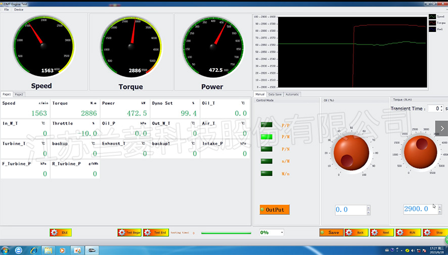
Engine test software interface
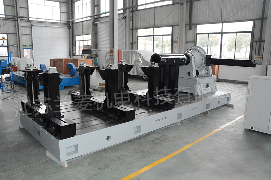
400kW engine test bench exported to UAE
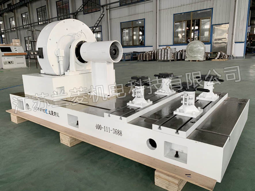
Exported to South Korea 315KW engine test bench
Japan Mitsubishi 100KW engine test bench
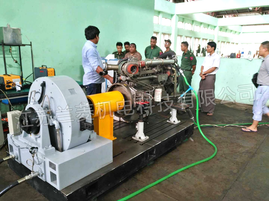
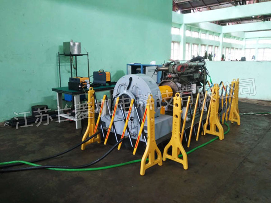
Burma military 300KW engine test bench
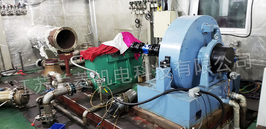
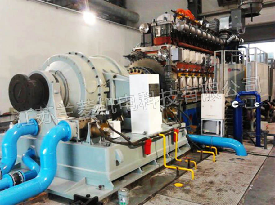
Shanghai Xinao Gas 630KW gas engine test bench
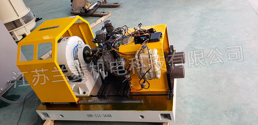
Zhenjiang Ferrui 100KW drone engine test bench
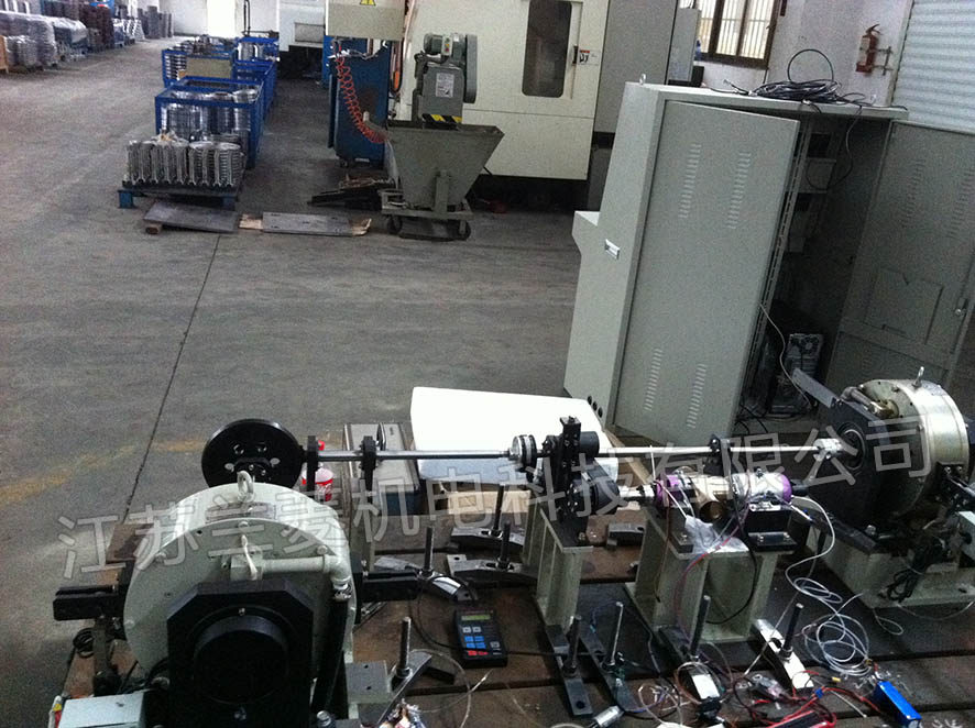
Northwest Polytechnic University 16KWX2 UAV engine test
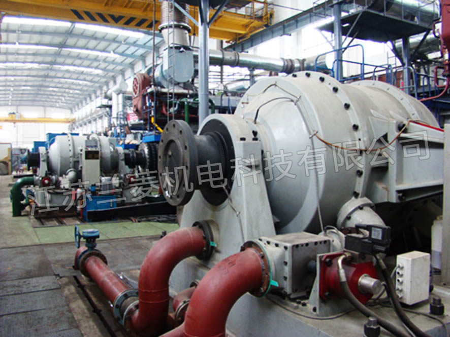
Exported to South Korea 3300kW diesel engine test bench

Exported to Romania CWC3000 engine test system
1. Basic situation of users
1. The basic information of the user unit is to be determined
2. Electricity: 50Hz, 380V±10%, three-phase five-wire system. (Grounding resistance is less than or equal to 4 ohms); Circulating cooling water: constant pressure supply of water tower, height ≥5m, water pressure of dynamometer ≥0.05MPa, natural cooling, water temperature ≤35°C.
3. Ambient temperature: air temperature 0~35℃, annual average temperature 20.4℃, absolute maximum temperature 38℃. Humidity: Relative humidity is 80%, and there is an average of 1 month per year for wet weather. Average annual rainfall: 800mm.
4. Test object: The main performance of the gasoline engine.
5. Project content
A set of eddy current dynamometer (or electric dynamometer) and performance test bench.
2. Project design basis
According to national, local, industry, and demand-side enterprise safety, environmental protection regulations and standards; homemade and domestically produced parts comply with GB standards, and ISO international standards are used equivalently or equivalently; special requirements parts are agreed by both parties, and users propose higher than the above standards The special requirements can be put forward in the relevant content of this document and covered by the above standard content;
Technical requirements, indicators and specifications beyond the above standards are proposed and implemented in the relevant content of this document.
3. Technical requirements of the project
1. Guiding ideology
According to the overall requirements for the design of eddy current dynamometer (or electric dynamometer) and performance test bench, Lanling Electromechanical Co., Ltd. carried out relevant design and installation of its bench project, so that the equipment system configuration quality is reliable, beautiful and tidy, stable performance, advanced technology , Cheap and good quality.
2. Technical requirements of engine test bench
Newly built standard engine test benches generally involve the following requirements according to general technology:
a. Design of engine test room (water system, power consumption, overall layout, etc.)
b. Fuel consumption meter
c. Dynamometer
d. Iron bottom plate
e. Air spring/shock absorber
f. Engine bracket
g. Dynamometer control and data acquisition and processing
h, start the power
i. Large screen in the compartment
j. Constant temperature of engine coolant
k. Data collection box
The console adds console, dynamometer and auxiliary supply system. The system uses the integrated drive unit, operation unit, and test unit to make the entire system a modular combination, which is convenient for equipment maintenance. After the bench is completed, it can be carried out: running-in test, idle speed test, speed regulation performance test, load characteristic test, speed characteristic test, reliability and durability test. The test specifications are implemented in accordance with GB/T19055-2003.
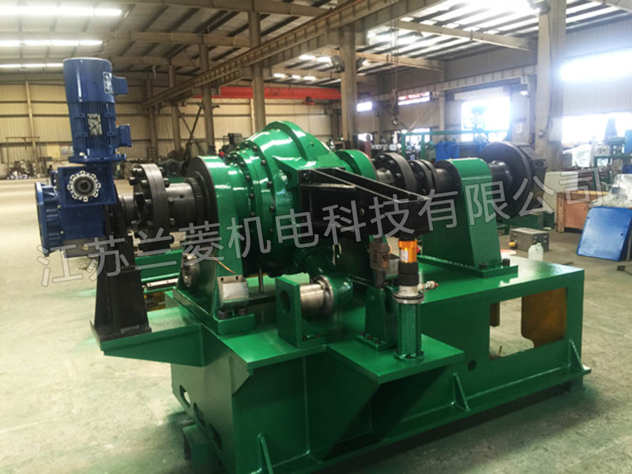
3. Loading device
The eddy current dynamometer adopts German technology and grease lubrication method, which is more suitable for medium and high speed engine test bench. It is a domestically produced eddy current dynamometer with relatively high cost performance.
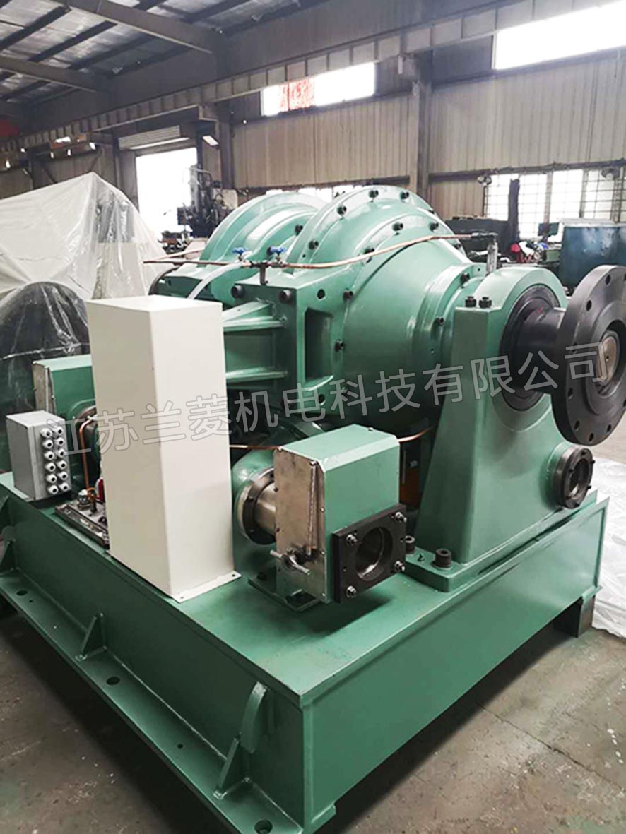
The electric dynamometer adopts domestic first-line brand or Siemens, ABB and other brand motors as the load, and during the loading process, the generated electric energy is fed back to the power grid, which can save 50 to 70% of the electric energy. The torque and speed sensor adopts 0.1% F.S grade produced by Lanling Technology, and can be sent to a third-party CNAS for certification. Customers can also specify foreign brands.
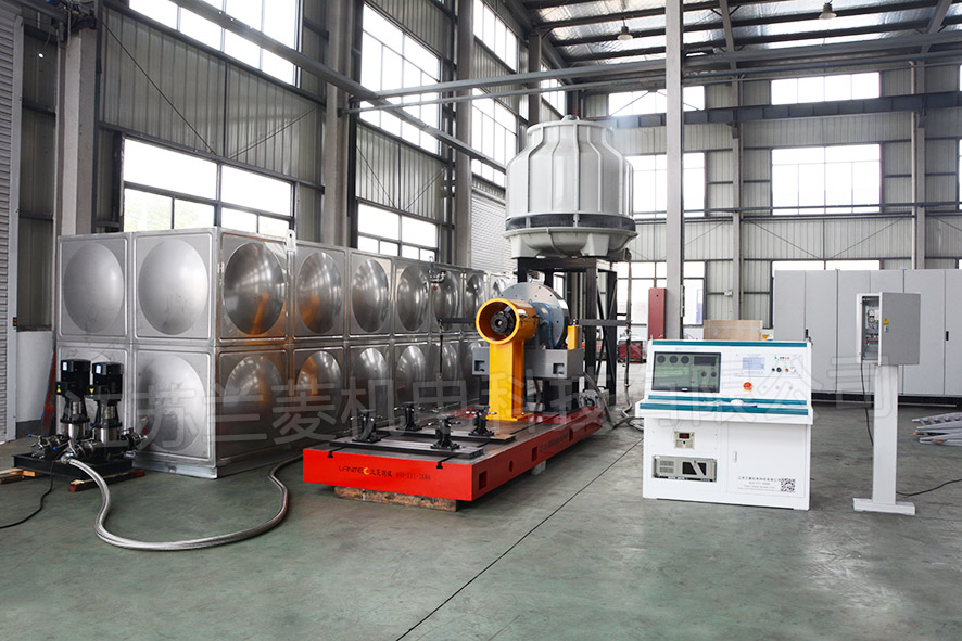
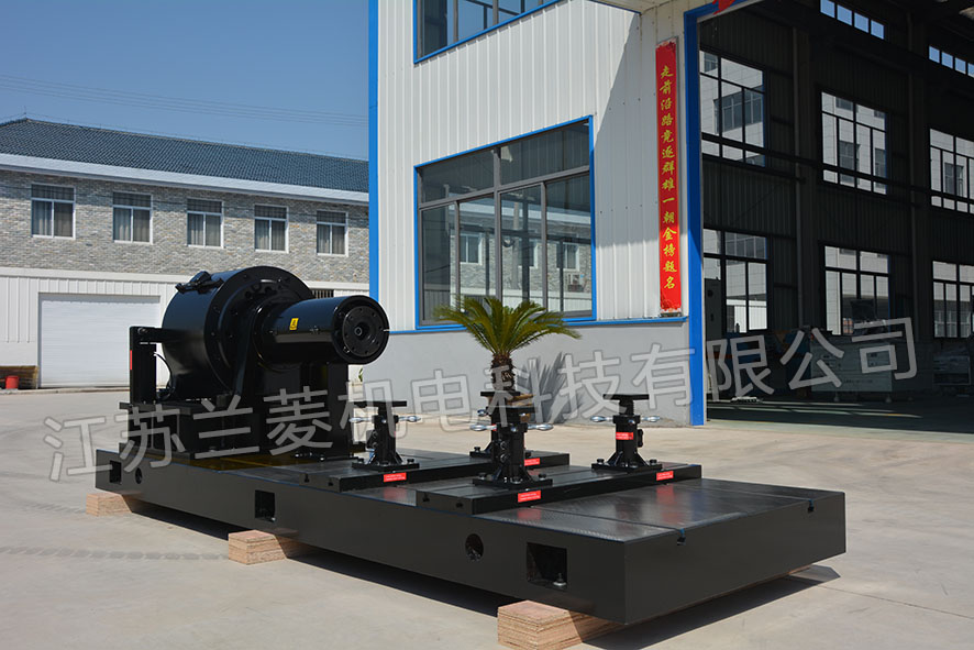
4. The overall bench composition of the dynamometer
The dynamometer bench is composed of a shock-absorbing pad, a large bottom plate, a dynamometer and a mounting base, connecting parts, and adjustable support for the engine.
A trapezoidal groove is formed on the large bottom plate, which is combined with the adjustable support of the engine, which can be adjusted arbitrarily in the three directions of X, Y and Z.
The dynamometer meets the high requirements of the center of the diesel engine by installing the base.
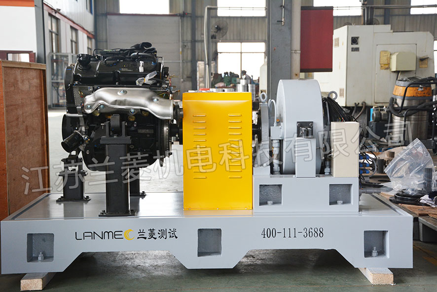
The connecting parts include engine connecting disk, splined shaft, splined sleeve, elastic coupling, auxiliary support, safety cover, etc. (or universal coupling), which has a certain flexibility and can easily meet the engine and dynamometer The alignment requirements of the device.
The function of the large base plate is to integrate the automobile engine, dynamometer and coupling and other components installed on the bench to ensure the correct position accuracy. And the whole is installed on the shock absorption foundation, so that the bench is more reasonable. The large bottom casting has a T-shaped groove on the plane. Bench cast iron large bottom plate reference size: 3000×1200×150. The foundation of the engine test bench is made of cast-in-place reinforced concrete, with a cast iron bottom plate (with T-bolt groove) and a pre-stressed elastic damper underneath. The technical indicators are as follows:
Rated load of shock absorber: 1200kg; rigidity: 550kg; natural frequency: 7Hz;
Deformation of shock absorber: 8-20mm; car engine test
No resonance or resonance occurs within the full speed range;
The maximum amplitude of the bench during the automobile engine test is less than 0.05mm, and the amplitude transmitted to the control room is less than 0.01mm.
Reference size of large base plate: 2500-3000×1200-1500×150-200.
5. Engine test machine bracket (performance bench)
It is used to support and fix the engine. The bracket is a welded steel structure. It is specifically designed and can be adjusted in three degrees of freedom, X, Y, and Z. It has a self-locking device to ensure speed and reliability.
6. The characteristics and main technical indexes of the throttle actuator and control system, and the throttle actuator control system of the engine emergency stop mechanism are as follows:
(1) The throttle actuator is fixed on the bench, and is connected to the engine throttle with a steel wire (link rod), or to the ECU simulation pedal.
(2) Throttle actuator motor is a rare-earth torque motor, with small size, large torque, rotation angle of 90o, output torque of 15NM, and response time of 0.4S.
(3) The digital regulator of the control system realizes high-performance automatic control of the engine speed. (Realization of control cabinet)
(4) The direct digital control (DDC) mode and flexible control algorithm of the control system can meet the measurement and control requirements of different types of engines.
(5) The control system has manual/program control functions (implemented by the control cabinet).
(6) The emergency stop mechanism is composed of a digital output module, a high-current power supply module, an emergency stop electromagnet, etc. It is used for manual engine stop, manual and automatic stop in an emergency.
7. Engine coolant constant temperature system
1) The factory test rig is equipped with closed circulation water tanks, pipelines, etc. to stabilize the temperature of the engine coolant inlet and outlet,
2) The technical parameters of the diesel engine cooling water closed constant temperature system and the closed diesel engine coolant constant temperature system for R&D bench:
The water temperature setting range is 45℃-95℃, any setting within the interval.
Temperature control accuracy: ≤±1℃ (engine water outlet temperature);
Pressure drop of engine coolant system: ≤0.038MPa.
Coolant constant temperature control device mainly consists of:
① Coolant replenishment device: expansion tank, water pump, solenoid valve
②Cooling device: heat exchanger, pneumatic (or electric) regulating valve
③Temperature setting and pressure setting control device
④Alarm device
8. Test control system
(1), system composition
The dynamometer measurement control system is mainly composed of engine dynamometer controller, data acquisition instrument, industrial control computer, horizontal console, etc.
(2), engine dynamometer controller
The measurement and control instrument is a horizontal desktop structure, which is composed of a console, a lower computer, and an upper computer. The upper and lower computers are built into the console. At the top right of the console is a digital window that displays the main parameters in real time. A 19-inch color liquid crystal display is embedded in the upper left of the console and fixed on the panel. The panel is oil resistant and flexible, showing the main and auxiliary parameters. The main and auxiliary parameters are matched according to the specified technical requirements.
Main functions of EDCS-Ⅰ measuring and controlling instrument lower computer
The system takes imported industrial industrial control microcontroller as the core, imported components, and the entire measurement control circuit adopts modular design, fully digital (DDC) setting and control.
High-precision strain-type tensile pressure sensor to achieve precise digital measurement of engine output torque;
The photoelectric speed sensor realizes high-precision instantaneous speed measurement;
It has the functions of random undisturbed switching control, sudden throttle unloading, and dynamometer load protection processing;
The measurement parameters can be set by the user in the computer for the action mode of each level of alarm.
Lower computer system control function
The dynamometer and engine throttle are controlled by dual loop direct digital PID, with the following automatic control functions:
Dynamometer: constant gate position, constant torque, constant gate speed (external characteristics),
Engine: constant throttle position, constant throttle speed.
The system control performance is shown in the table below
No. Control mode Control accuracy Overshoot amount Reference accuracy Response time
1 Water gate constant position ±0.2% FS±1dp ≤step amount 0.5% ≤0.1%. <5 seconds
2 Constant torque ±0.2%FS±1dp ≤step amount 1% ≤0.1%. <10 seconds
3 External characteristics ±0.2%FS±1dp ≤step amount 1% ≤0.1%. <10 seconds
4 Throttle constant position ±2 r/min±1dp ≤step amount 0.5% ≤0.1%. <5 seconds
5 Throttle constant speed ± 2r/min ± 1dp ≤step amount 0.5% ≤0.1%. <10 seconds
(3) Configuration and main functions of the host computer control system
The host computer selects Advantech industrial control computer, and the industrial control computer and required boards use well-known brands. Send the reserved serial port that can be expanded to the user for future use, and integrate it into the computer system according to the communication protocol provided by the user.
Industrial computer configuration: Cool dual-core 2.6G or more, RAM: 1G, hard disk: 250G, 10/100M adaptive network card, 19-inch LCD display, RS232/485 expansion card.
Record function
The control system needs to upload and store the measurement data and fault information in real time. Automatically save the data to the network database, temporarily save the data to the local database when the network database fails, and then dump to the network database when appropriate.
Automatically generate reports and curves.
Alarm protection function, the measurement control system has three levels of alarm and protection functions, and each measurement parameter can be set by the user in the computer for the action mode of each level of alarm:
First-level alarm: sound and light alarm, the system does not act, manual intervention;
Second-level alarm: sound and light alarm, system action, engine operating conditions automatically reduce to idle speed;
Three-level alarm: sound and light alarm, system action, stop the engine through emergency stop mechanism.
The test bench is equipped with a parking electromagnet. In the event of a failure, press any emergency stop button, and the parking electromagnet cuts off the oil path (the rear of the fuel consumption meter).
The entire host computer control system takes configuration-specific software as the core, and is equipped with software such as test condition editing, test data processing, and test process control. The data exchange between the upper and lower computers is realized through the field bus, and the entire engine test control process is completed. Data processing and screen display. All measurement parameters can be displayed on the liquid display. Display mode: digital display and curve display. Torque, power and fuel consumption can be automatically corrected by the computer, and the correction formula can be automatically selected according to the model (according to the national standard GB/T18297-2001), or it can be calculated by the operator.
According to the set steps, it automatically completes various program control tests. The combination of steps can be arbitrarily combined according to the experiment. The measured data is calculated, corrected, statistically analyzed and output for power, torque and fuel consumption according to JIS standards and GB/T6072.1-200 national standards.
Various general test characteristic curves and test data reports can be automatically generated on the computer screen (Word or Excel format can be exported).
The software uses plug-and-play design technology, and the user adds, deletes, edits, adjusts, and displays measurement parameters. The software is easy to expand without the need to modify the original program; it has self-learning and self-organization functions, self-expansion of the engine failure database, self-memory of user operation frequency, and automatic judgment of all man-machine dialogues required to give the optimal The solution has a fault recording function and gradually realizes humanized operation.
Main technical indicators of test bench measurement parameters (optional according to user needs)
No. Parameter name Measurement range Resolution Measurement accuracy Adapted sensor
1 Speed 0-3000r/min 1r/min ±0.1%F.S ZSD speed sensor
2 Torque 0-3000N.m 1N.m ±0.2%F.S+1d 150kg load sensor
3 Fuel consumption 0-2000g 0.1g ±1%F.S+1d>2kg load cell
5 Oil pressure 0-1MPa 1kPa ±1%F.S+1d 4-20mA pressure transmitter
6 Oil temperature 0-2000C 10C ±1%F.S+1d PT-100 thermal resistance
7 Exhaust temperature 0-8000C 10C ±1.5%F.S+1d K index thermocouple
8 Inlet water temperature 0-2000C 10C ±1%F.S+1d PT-100 thermal resistance
9 Outlet temperature 0-2000C 10C ±1%F.S+1d PT-100 thermal resistance
10 Throttle opening 0-100% ±1% linear 2% WDD22D
11 Dynamometer current 0-100% ±1% linear 2% WDD35D-1
12 Outlet temperature after vortex 0-8000C 10C ±1.5%F.S+1d K index thermocouple
13 Intercooling temperature 0-2000C 10C ±1%F.S+1d PT-100 thermal resistance
14 After-cooling temperature 0-2000C 10C ±1%F.S+1d PT-100 thermal resistance
15 Intercooling front pressure 0-250kPa 1kPa ±1%F.S+1d 4-20mA pressure transmitter
16 After-cooling pressure 0-250kPa 1kPa ±1%F.S+1d 4-20mA pressure transmitter
17 Exhaust pressure after turbine 0~300KPa ±1%F.S+1d 4-20mA pressure transmitter
18 Exhaust pressure before turbine 0~300KPa ±1%F.S+1d 4-20mA pressure transmitter
19 Turbocharger speed 0-200000r/min 10r/min ±1%
20 Atmospheric humidity 0-100% 1RH% ±3% F.S+1d JWSL-2AT
21 Atmospheric temperature 0-500C 10C ±1%F.S+1d JWSL-2AT
22 Atmospheric pressure 0-100kPa 1kPa ±1%F.S+1d JQYB-1N
9. Transient fuel consumption meter
The fuel consumption meter uses transient measurement fuel consumption meter (including fuel temperature control system).
Transient fuel consumption meter (including fuel temperature control system) uses the latest technology Coriolis (Coriolis) to directly measure mass flow.
High-precision 0.1-level continuous measurement, response time is less than 0.1 seconds.
The measurement accuracy is less than 0.10% of reading.
Intelligent, on-site configuration, multiple signal output.
The range is wide, suitable for a variety of power grade engines.
With automatic bubble removal function.
With fuel constant temperature function, the control accuracy is ±0.5℃.
Rated flow quality: 0-150kg/h
Maximum flow quality: 350 kg/h
Zero drift: 0.0224 kg/h
Accuracy% (reading value): 0.12%
Repeatability% (reading value): 0.05%
Maximum circulating oil supply: 800 kg/h
Cooling power: 6kW
Maximum temperature control range: 10-80℃
Heating power: 3kW
Maximum power consumption: 10kW
Takeover size: DN 16
Mass: 80 kg
Applicable engine power: below 200kW
Coriolis flowmeter system functions
Response time: T10...T90<1S.
Measurement display
|