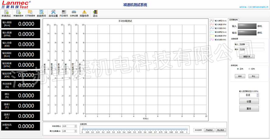
Worm gear box efficiency test software
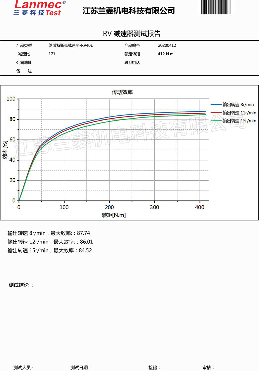
Worm gear box test report
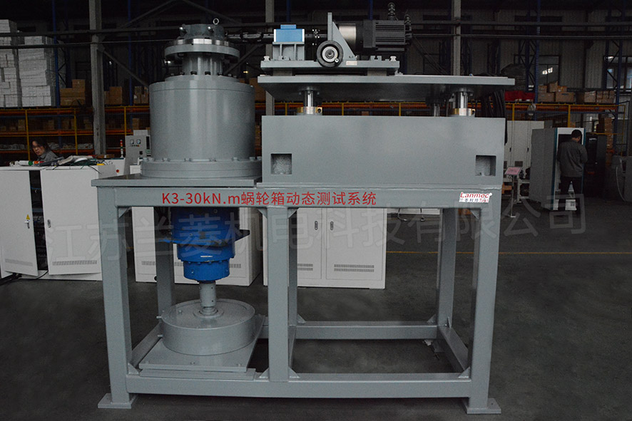
Jiangsu Dongkuo 30kN.m/120kN.m Worm Gear Box Test Bench
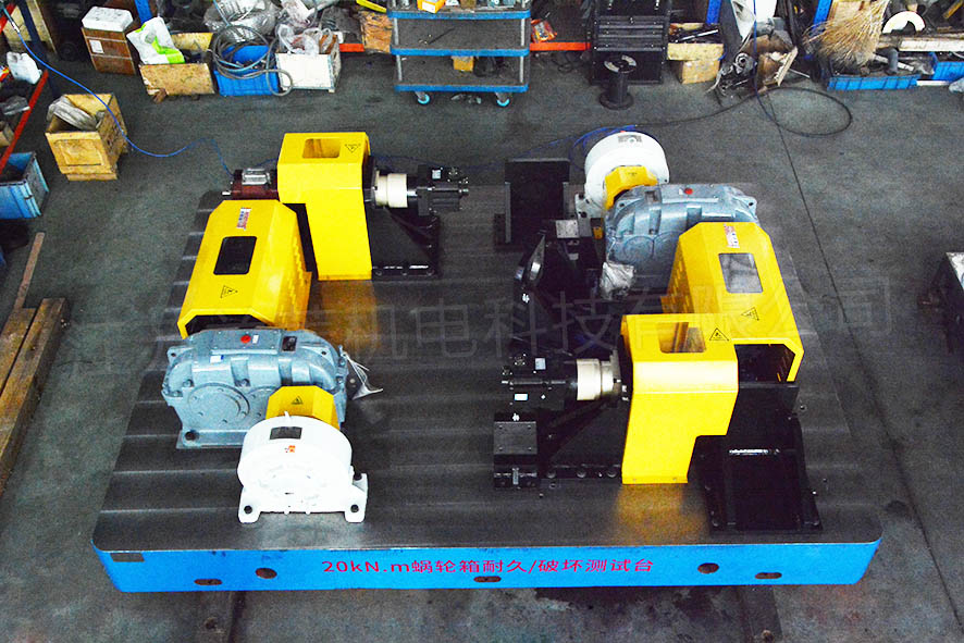
Tianjin Linsai 20kN. m Worm Gearbox Durability/Damage Test Bench
Quanzhou Chaoyue 300KN. m Worm Gear Box Load Durability Test System
50K&300KN.m Worm Gearbox Loading Test Bench for Changzhou Power Station Auxiliary Machine
300KN.m worm gear box loading test stand of Yangzhou Electric Power Repair and Manufacturing Plant
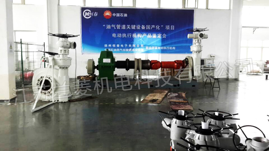
Yangzhou Hengchun 300,000 N.m
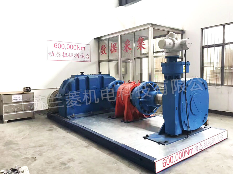
Shanghai Qizhong 600KN.m worm gear box loading test stand
Zhejiang Xunjie 5000&50000N.m Worm Gearbox Efficiency Test Bench
Zhejiang Weibo 30KN.m Worm Gearbox Efficiency Test Bench
Xibosi 100KN.m worm gear box efficiency test bench
Zhejiang Dagong 300KN.m Worm Gearbox Efficiency Test Bench
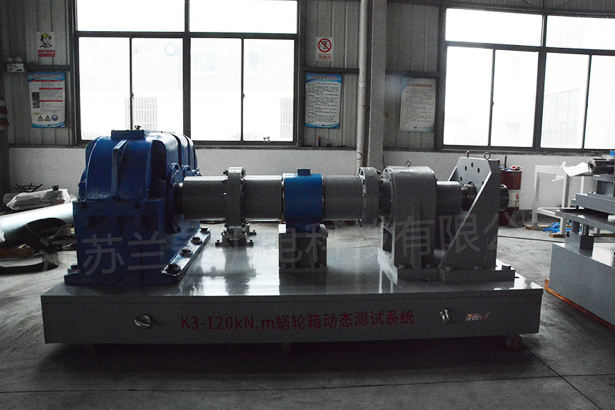
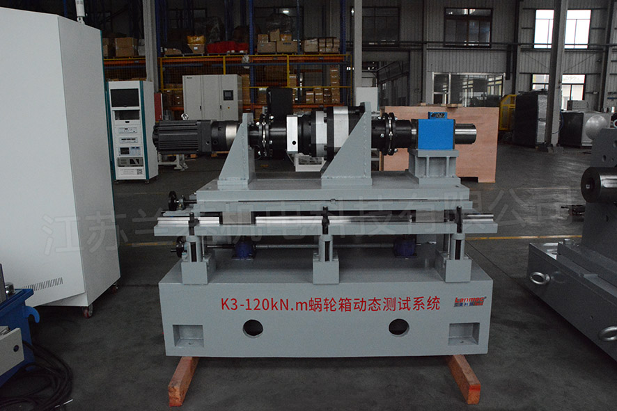
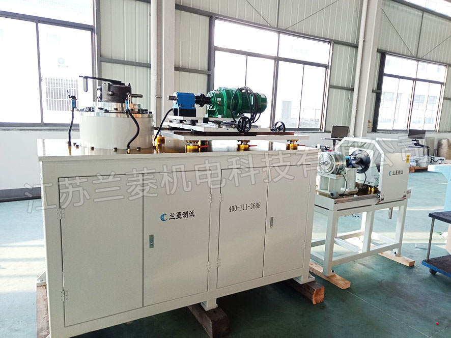
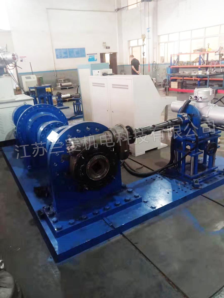
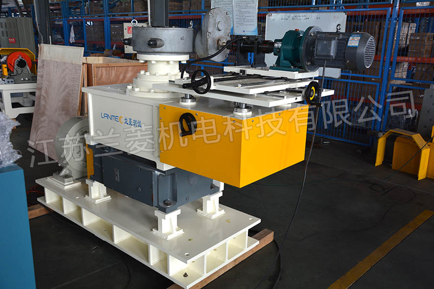
1. Introduction of worm gear box load endurance test system
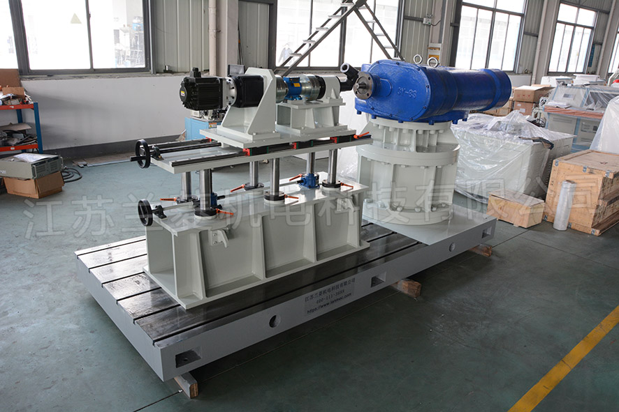
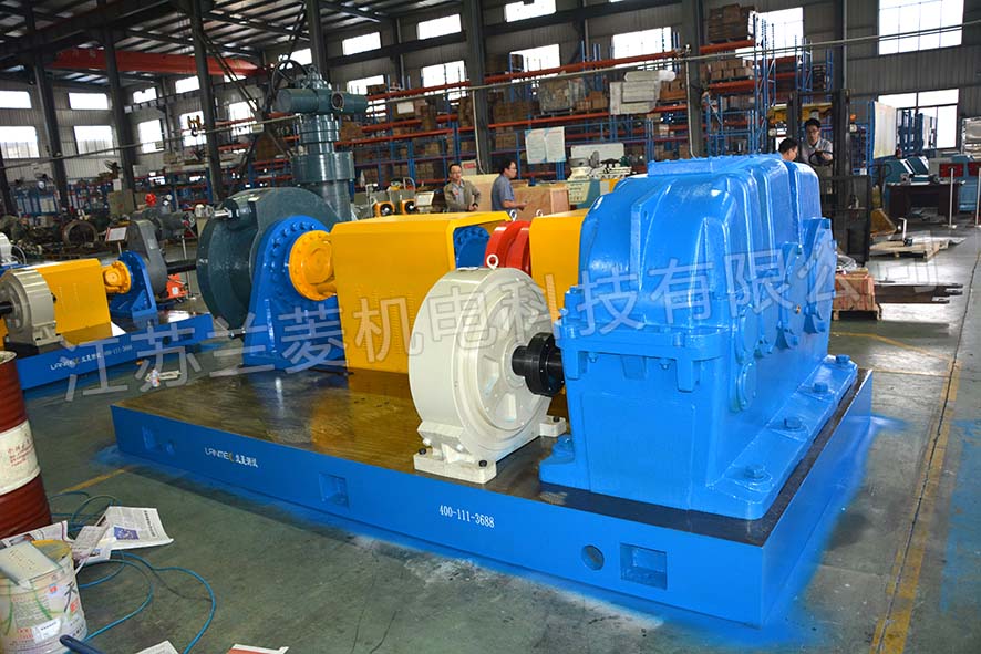
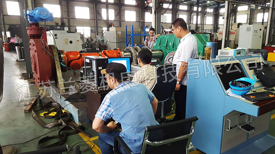
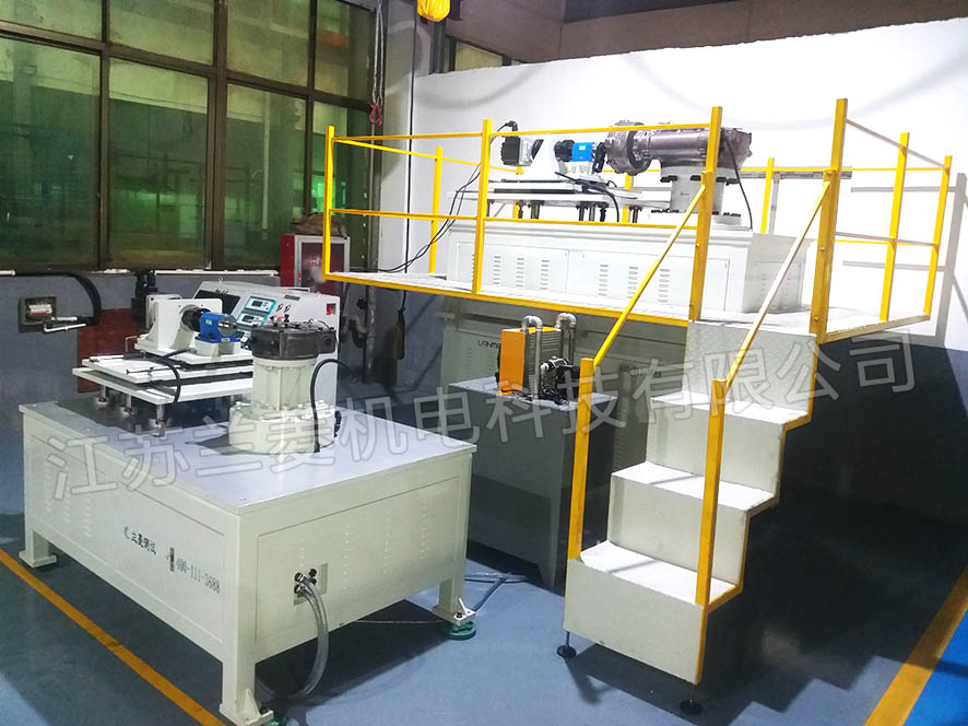
Worm gear box load endurance test system consists of 3Kw servo motor/speed ratio 1:43 planetary reducer (power)-500N.m input-end torque and speed sensor-worm gear box-output-end torque and speed sensor-loading device, test bench, Actuator installation fixture, inspection cabinet, etc., it can arbitrarily change the load of the electric actuator under test and directly measure:
Worm gear box input torque, speed, power
Torque, speed, power output by worm gear box
Worm gearbox efficiency and speed ratio
2. Test parameters:
Torque: 5000-1000KN.m
3. Test accuracy:
Mechanical: ±0.2% F.S (torque, speed, power)
Efficiency: ±0.2% F.S
Angle: ±1°
4. Software function:
The worm gear box test software is a data acquisition software based on PC (Windows 7 SP1) used to test the performance of the worm gear box. The test software can be used to manually test, automatically load, curve load, fixed-point test, endurance test and other test items of the valve under test in conjunction with electrical parameter instruments, torque and speed acquisition instruments, and program-controlled loading instruments. The data is automatically stored and the test curve is dynamically generated. Multiple curves can be selectively displayed for data comparison. The measured data are saved in a database file in the format of .db for user query. The software can export the data as PDF, Word graphic report or Excel format data file to the personal computer according to the settings.
The specific functions are as follows:
4.1 Can display, save and print:
Torque, speed, power input of the tested worm gear box
Output torque, speed, power; efficiency; speed ratio; rotation angle
Various parameters and the curve relationship between them, and form a report to save and print
4.2 Life test, contact output. It can send commands to command the start and stop of the cyclic action of the actuator; the panel and the host computer can switch to control the action of the actuator.
4.3 Loading method: manual, program-controlled loading
5. Division of Labor
A. Party B is responsible for:
Install the connecting cable from the test cabinet to the test bench.
The two parties cooperate in the joint commissioning of the inspection cabinet, test bench, actuator, and worm gear box.
B. Party A is responsible for:
Cable and installation, including:
Single-phase AC220V500W50HZ power supply-detection cabinet.
Three-phase AC380V3000W50HZ power supply-detection cabinet.
Transport the goods from the factory gate to the installation site and adjust the level.
Design and manufacture of connecting flanges and connecting shafts of other specifications of worm gear box (Party B only provides universal flange interface and shaft interface, and provides a test tool and coupling of a worm gear box for debugging).
6. Delivery time: advance payment to 90 days delivery
7. Pre-acceptance (all provided by Party B for free)
Machine acceptance
Party A provides the tested worm gear box, which is installed on a complete set of test benches to carry out the dynamic test of loading, and observe whether the loading and display are normal, and whether there is abnormal vibration and noise.
8. Party B provides factory information:
Calibration report of torque speed sensor
Machine, instrument, software instruction manual
Software CD
Certificate of conformity, three guarantees.
9. Final acceptance
After the equipment has been commissioned on site by Party A, both parties will conduct final acceptance of the machine, electrical and software of the equipment. After passing the test, both parties will sign and confirm, and the unqualified items will continue to be rectified until they are qualified. (The software can be confirmed in advance during the pre-acceptance)
10. After-sales service
Within 12 months after the acceptance of the dynamometer (the torque and speed sensor is 24 months), if all parts and instruments fail (not caused by man-made), three guarantees will be implemented. The courier replacement that can be replaced by express delivery can be resolved by phone. The phone can't solve it. Party B needs to arrive at the site within 48 hours. For equipment failures caused by reasons other than Party B, material costs, road expenses, and labor hours will be charged at cost. After 12 months, Party B will arrive within 48 hours to use the on-site paid service.
11. Commissioning training
After receiving the call from Party A for debugging, Party B must arrive at the site of Party A within 48 hours, and the debugging is completed within 3 days. During this period, the operator of Party A can be trained free of charge.
|