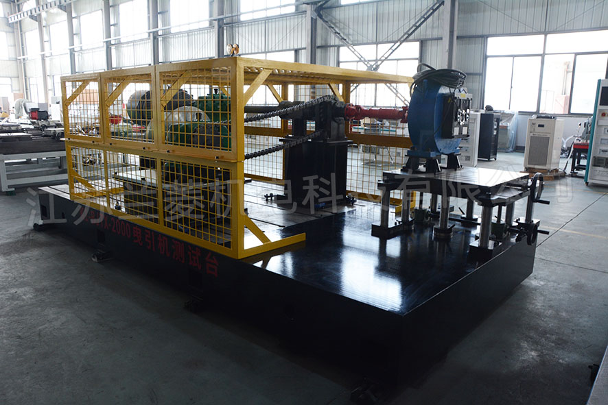
Chengdu 2000N. m traction machine test bench
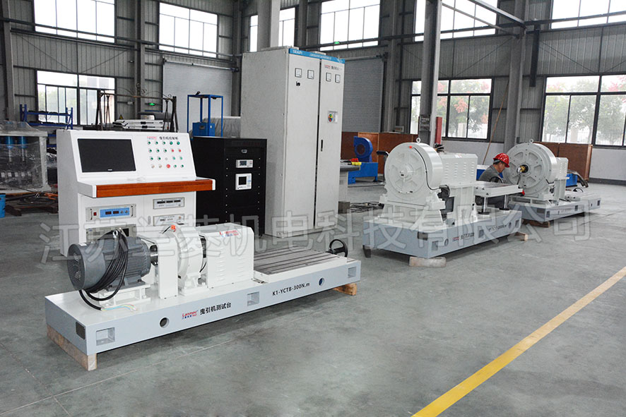
Zhejiang Fuld 300N.m 2000N.m 5000N.m Traction Machine Test Bench
Guangzhou Otis 5000N.m traction machine test bench
Shanghai Thyssen 2000N.m 30KN lifting-radial force synchronous simulation test bench
Shanghai Thyssen 5000N.m traction machine inertia test bench
Suzhou Rui drive 2000N.m traction machine test bench
Shanghai Monterey 5000N.m traction machine test bench
YTI 2000N.m traction machine test bench
Shanghai Schindler 2000N.m traction machine test bench
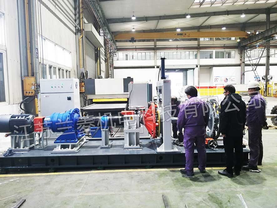
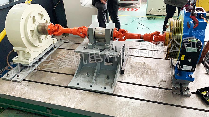
Hangzhou Xizi 60KN.m main drive brake torque test bench
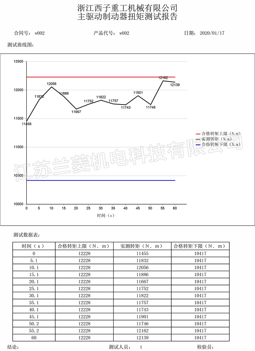
Hangzhou Xizi 60KN.m main drive brake torque test report
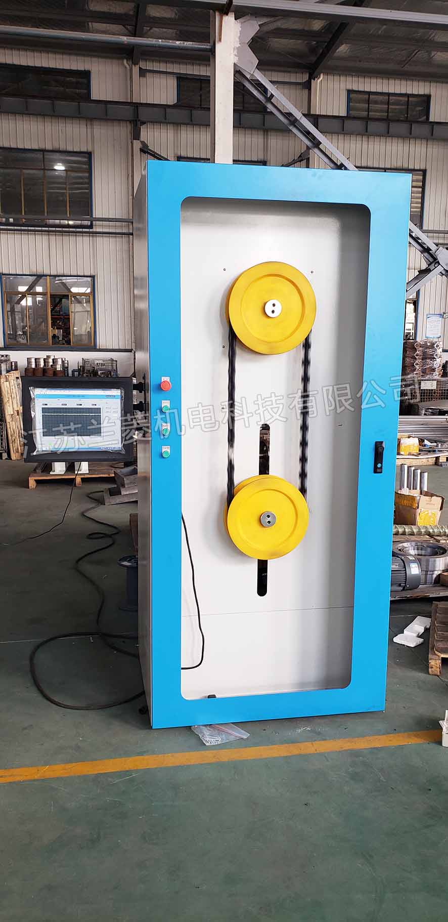
Xinghua tape 15Kg balance chain life test bench
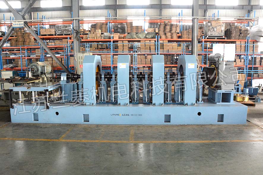
SHDS-5000GL traction machine load test bench
1. Directory/Contents
1 Scope
2 Normative references
3 Technical requirements 1
3.1 Test bench model 1
3.2 Basic parameters 1
3.3 Basic composition 1
3.4 Functional requirements 1
3.4.1 Casting material 2
3.4.2 Accuracy requirements 2
3.4.3 Casting requirements 2
3.4.4 Inertia requirements 2
3.4.5 Torque sensor protection requirements 2
3.4.6 Lifting platform 2
3.4.7 Load motor 2
3.4.8 Tractor under test 2
3.4.9 Protection 2
3.4.10 Checking the drawings of the test bench 2
2. Scope
This standard specifies the technical conditions and quality requirements of the SHDS-5000GL traction machine load test stand (structural part).
Normative references
The clauses in the following documents become the clauses of this standard through quotation from this standard. For dated reference documents, all subsequent amendments (not including errata content) or revisions are not applicable to this standard. However, parties that have reached an agreement based on this standard are encouraged to study whether the latest standards of these documents can be used. For the cited documents without date, the latest version is applicable to this standard.
GB/T9439-2010 gray cast iron parts
GB/T22095-2008 cast iron flat plate
GB/T6414-1999 National Standard Casting Tolerance Standard
GB/T11351-1989 Quality tolerance of castings
JB/T7974-1999 cast iron flat plate
3. Technical requirements
Test bench model
Model: SHDS-5000GL
The test bench should be able to withstand the force of the traction machine under sudden load increase and decrease.
The test stand can withstand the force of the traction machine at a maximum output of 5000Nm torque and a maximum speed of 500r/min.
Measurement parameters
The current, voltage, power factor, and electric power input by the traction machine; the torque, speed, and power output by the traction machine; the efficiency of the traction machine; temperature rise; radial force.
Measurement accuracy ��0.2%F.S
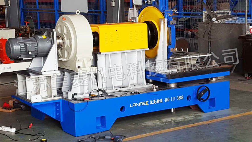
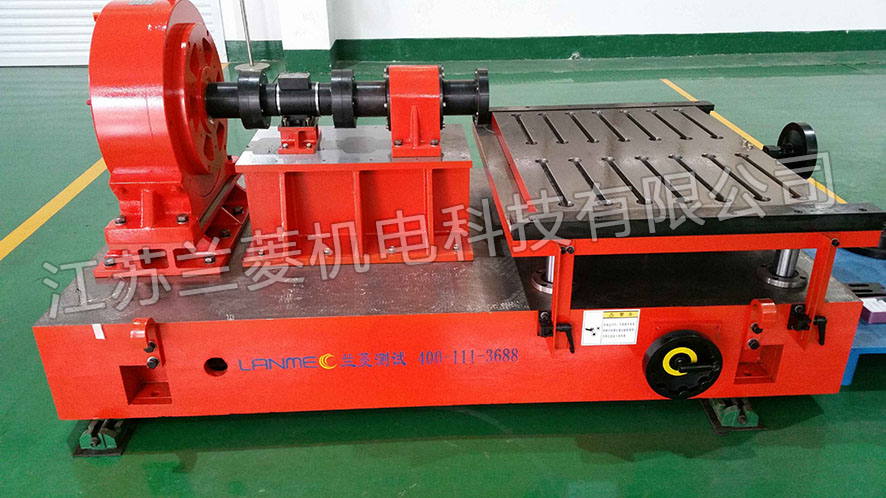
Fourth, the basic composition
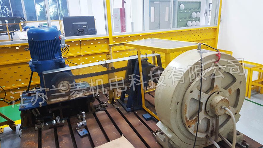
The test bench consists of a casting platform, a lifting platform, an inertia disc, a torque sensor, a load motor, and a traction machine under test.
V. Functional requirements
Casting material
The material of the casting platform is HT250, the hardness range is HB190-HB240, and the hardness difference does not exceed HB30.
Accuracy requirements
Casting platform accuracy level: 1 level.
Casting requirements
Castings shall not have defects such as pores, blisters, sand inclusions and shrinkage.
Castings should be aged.
Casting shall meet the requirements of design drawings.
The processing of the casting platform is strictly in accordance with the machining process, and the entire flatness error of the platform should be less than 0.02mm.
The processing surface of the casting platform is coated with anti-rust paint, the non-processed surface is coated with primer and topcoat protection, and the coating should be firm.
Inertia requirements
The load test stand can add 10~300Kg.�O inertia, 4 50Kg.�O inertia discs, 10, 20, 30, 40Kg.�O inertia discs each. It is required that the inertia disc can be added by electrical control. The inertia disc should have sufficient strength support at both ends, and it should not affect other components during operation.
Torque sensor protection requirements
The torque sensor is provided by the purchaser, and the T40B 5kN and T40B 3kN sensors of the German HBM company are used. For the sensor manual and installation dimensions, see the attachment. German HBM will provide on-site technical support when installing sensors.
Due to the different dimensions of T40B 5kN and T40B 3kN, please match flanges of different sizes so that the two specifications of sensors can be installed interchangeably.
It is required that the connecting part of the torque sensor has effective protection and should not be subjected to axial and radial forces.
At least one of the couplings on both sides of the torque sensor is an elastic coupling.
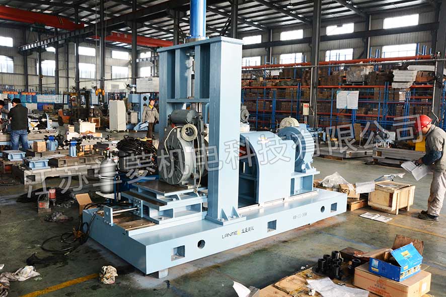
Lifting platform
The tested traction machine is installed on the lifting platform. The lifting platform should be able to adjust up and down and left and right, the center height adjustment range is 150~500mm, and it moves 100mm back and forth. There should be a tightening device, which should be tightened when the test bench is running. The tightening device should have sufficient strength.
Load motor
The load motor is provided by the buyer, the maximum output torque of the motor is 5000Nm, and the maximum speed is 500r/min. See attachment for motor mounting dimensions.
Tested traction machine
See the attachment for the installation dimensions of all tested traction machines, which requires that the traction machine can be tightened and tested on the lifting platform.
Protection
The rotating part of the test bench should be effectively protected, and the protection does not affect the replacement of the disassembled part.
Checking the drawings of the test bench
All drawings should be submitted to our company for review regularly, including strength calculation data.
6. Technical Information
1. Drawing materials
1.2. Electrical schematic
1.3. Assembly drawing and electrical wiring diagram of equipment parts
1.4. Equipment wear parts list and drawings, purchased parts list and model.
2. Technical documents
2.1. Equipment safety operation regulations
2.2. Equipment operation (use, maintenance) manual
2.3. Technical documents
2.4. Software information files
Seven, technical training, service, installation and commissioning and warranty period
1. Technical training
The supplier shall do the following technical training to the user during final acceptance:
1.1. Equipment installation training
1.2. Training of electrical control design principles (including: protection, monitoring, fault display, etc. in electrical design)
1.3. Training on equipment operation, repair and daily maintenance
1.3. Training on common faults and special faults of equipment
1.4 Only after all the above items are qualified, the technical training is considered qualified
2. Technical services
2.1. Scope of service: When the equipment fails during the warranty period, the supplier will provide free maintenance for the user within the shortest time.
2.2. Repair and replacement of spare parts. When the equipment fails after the warranty period, the supplier still repairs the user for free. Replacement of spare parts is required
Charge costs.
2.3. Service response time: within 4 hours
2.4. Time for service personnel to arrive at the demand-side work site: within 24 hours
2.5. Conduct technical training work such as operation and maintenance on the demand side
3. Installation, commissioning and warranty period
3.1. Within 90 days after the delivery contract is signed and the prepayment is received.
3.2. The installation period is about 7-10 working days.
3.3. The equipment is responsible for three guarantees for 1 year from the date of final acceptance
|