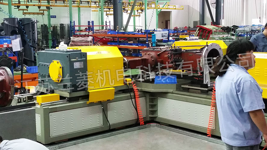
JAC Power 2X2000N.m front and rear axle loading test bench
Jiangsu Changfa 2X2000N.m front and rear axle loading test bench
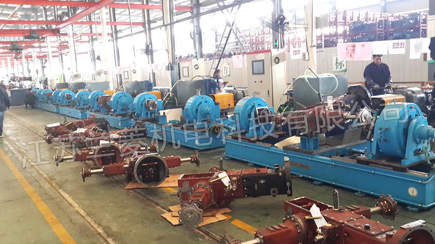
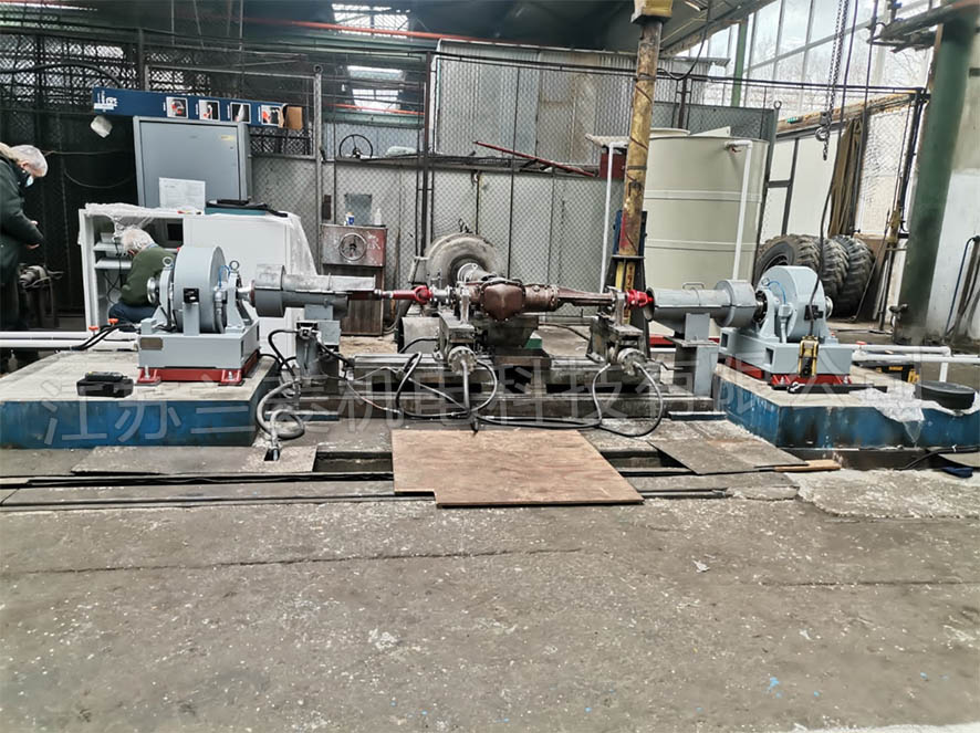
Jiangsu Changfa 22-100KW (A.C.D.G.H) tractor chassis transmission system
Jiangsu Wode 22-100KW (A.C.D.G.H) tractor chassis transmission system
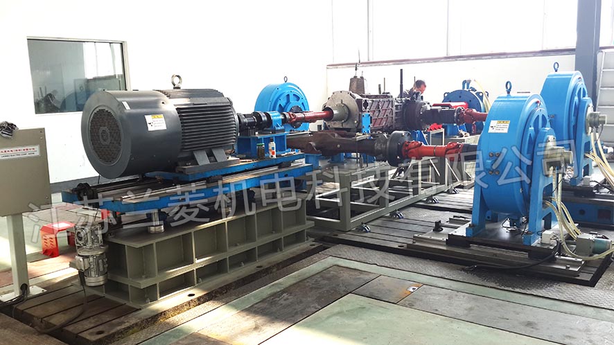
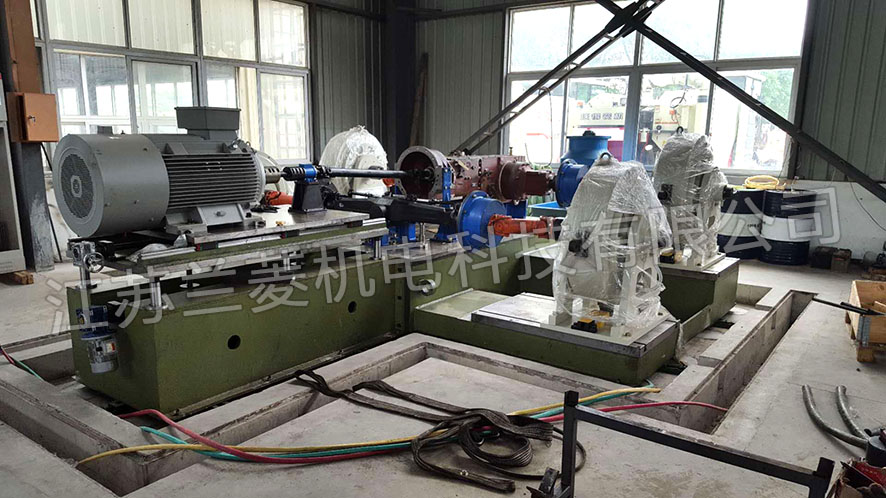
Exported to Romania DW-160 axle double-side loading test system
22-100KW Tractor Chassis Transmission System Comprehensive Test Bench
Technical Solution Specification
table of Contents
1. Design basis
2. Test object
3. Research project of test bench
4. Main technological parameters of specimen test
5. Main functions of test bench equipment
6. The main technological parameters of the test bench equipment
7. Equipment use environment
8. Test bench description
9. Equipment List
10. Delivery time
11. After-sales service
12. The buyer needs to prepare
13. Commissioning
14. Transportation
15. Liability for breach of contract
1. Design basis:
"Jiangsu Lanling Electromechanical Technology Co., Ltd. Technical requirements for tractor chassis transmission system comprehensive test bench"
2. Test object:
22-100KW (A.C.D.G.H) indoor load running test of tractor chassis transmission system
3. Test items of the test bench:
3.1 No-load test of tractor chassis
3.2 Chassis loading test (front axle + rear axle + PTO)
3.3 Chassis loading test (rear axle + PTO)
3.4 Chassis loading test (front axle + rear axle)
3.5 Chassis loading test (front axle)
3.6 Chassis loading test (rear axle)
3.7 PTO loading test
3.8 Differential speed test of transmission system
3.9 Transmission system efficiency test
3.10 Test of load closed-loop system
4. Main technological parameters of specimen test
Drive power variation range 22-100KW
Input speed range 0-2400r/min
Speed measurement accuracy ±1r/min
Rear axle loading torque measurement range 300-10000N.m*2
Front axle loading torque measurement range 300-5700N.m*2
PTO loading torque measurement range 60-2000N.m
Torque measurement accuracy ±0.5%
Temperature measurement range -50 ― 200℃
Temperature measurement accuracy ±1%
Torque control accuracy ±0.5%
Speed control accuracy ±0.5%
Total output power ±0.5%
5. Main functions of test bench equipment
5.1 Closed-loop control drive system. Frequency conversion stepless speed regulation.
5.2 Numerical control loading load.
5.3 The transmission system can realize automatic and manual test operation.
5.4 The test control system can control 1 and 5 drive motors during automatic and manual testing.
Load motor, realize two-wheel drive loading on the rear axle, two-wheel drive loading on the front axle, four-wheel drive loading (two on the front axle)
Drive, two drives of the rear axle are loaded at the same time), five drives are loaded (two drives of the front axle, two drives of the rear axle, power
The output shaft is loaded simultaneously) and the power take-off vehicle (PTO) is loaded. Braking can be performed during the test,
Efficiency, torque, speed and temperature test under three conditions of unilateral braking and differential speed.
5.5 Display, processing and analysis of the types of various tests.
5.6 Collect, process, store, output, and print test data for various tests.
5.7 Control system settings: automatic, manual.
5.8 Measurement and control system settings, over current, over pressure, overload, over temperature, fault automatic alarm system
Protective function.
6. The main technological parameters of the test bench equipment
6.1 Drive power 110KW
6.2 Maximum input torque 670N.M
6.3 Maximum speed: 3000r/min
6.4 Rated nominal speed: 2400r/min
6.5 Rear axle loading power 37KW x 2
6.6 Rear axle loading speed-up ratio i = 28.5: 1
6.7 Maximum loading torque of rear axle wheel side 10005.99 N.M x 2
6.8 Front axle load power 22KW x 2
6.9 Front axle loading speed-up ratio i = 28: 1
6.10 Maximum loading torque of front axle wheel side 5876.6 N.M * 2
6.11 Power output shaft (PTO) loading power 110KW
6.12 PTO load-to-speed ratio i = 2:1
6.13 Maximum load torque of power output shaft (PTO) 2122 N.M
7. Environmental requirements for equipment use
7.1 Power supply: three-phase four-wire system Voltage: 380V±10V Frequency: 50HZ±5HZ
Total installed power: 120Kw
7.2 Water source: pressure ≥ 0.2MP
7.3 Compressed air: 0.6MP ± 0.1
7.4 Ambient temperature: 0℃-40℃
7.5 Ambient humidity: ≤90%
8. Test bench description
8.1 Plan of electrical cabinet
8.2 Mechanical part plan
8.3 Installation/connection of front and rear axles
Each model is equipped with a fixed bracket (a total of 5 brackets), positioning the front and rear bridges on the large flat plate, and the distance between each other is also fixed. It is fixed on the large flat plate by screws or pressing plates. Borrow the drive shaft and bracket on the rear axle, and connect to the power input shaft of the front axle through the telescopic universal joint.
8.4 Configuration and installation of main drive
8.4.1 Drive the rear axle
Drive: 110Kw2-level frequency conversion motor + ZJ-1000A torque speed sensor + transition seat + high-precision transmission shaft + universal joint is connected to the double spline sleeve. The double spline sleeve is connected to the support flange through 2 bearings. There is a cooling mechanism on the outer ring for cooling when the bearing temperature is high. The supporting flange is positioned by a cylindrical pin and fixed by an external hexagonal screw to avoid double splines from receiving bending moments. The motor is installed on the linear guide rail, and it can be moved forward and backward through the hand crank of the lead screw. The center height of the motor platform can be adjusted manually up and down, four linear bearings and guide columns keep the motor shaft parallel, and the two lifting reducers save the balance at both ends.
The middle of the coupling is connected by polyurethane plum blossom pads, the center adjustment is more convenient.
The motor moves back and forth using linear guide rail plus screw handwheel/reduction motor
The motor lift table uses four linear bearings and guide columns to keep the motor shaft parallel, and the two lift reducers preserve the balance at both ends
8.4.2 Drive the front axle
Drive: (the front axle input speed is 0-1440rpm, the maximum torque is 5876.6N.m (single side))
110Kw 4-level frequency conversion motor + ZJ-1000A torque speed sensor + transition seat + universal joint is connected with the front axle spline. The motor is installed on the linear guide rail, and it can be moved forward and backward through the hand crank of the lead screw. The center height of the motor platform can be adjusted manually up and down, four linear bearings and guide columns keep the motor shaft parallel, and the two lifting reducers save the balance at both ends. When the front axle is tested separately, the installation method of the front axle is opposite to that when the four-wheel drive is tested together, and the input shaft is installed in reverse. The input power part is connected to the front axle through a lifting mechanism to lower the center height of the input shaft.
8.5 Configuration and installation of front and rear axle tests
The CFC-10000 magnetic particle dynamometer is connected to the drive wheels on both sides of the front and rear axles through a telescopic universal joint. When designing the gantry, the center height of the left and right drive wheels of each front and rear axle should be as close as possible to the center height of the magnetic particle dynamometer. The magnetic powder dynamometer moves forward and backward as a whole and is connected to the left and right wheels with a telescopic universal joint. The magnetic powder dynamometer is installed on the linear guide rail, and can move forward and backward through the screw and the reduction motor. When the equipment is fixed, determine the position of the magnetic particle dynamometer according to the largest front and rear axle size, try to ensure the coaxial consistency of the corresponding front and rear axle dynamometer. For the small model front and rear axles, increase the length of the power input part universal joint And the rear axle enters the length of the front axle drive rod to ensure installation.
8.6 PTO test configuration and installation
Passed CW2000C eddy current brake loading + ZJ-2000A torque speed sensor test, connected to PTO through telescopic universal joint. The whole can move back and forth and up and down.
8.7 Cooling device
Flow rate 60L/min, volume 36m3, pressure 0.1-0.3Mpa
8.8 Electrical description
drive:
A 110Kw inverter (Mitsubishi) drives a 110Kw class 2 Siemens motor, and the torque and speed of the motor are accurately controlled by a Siemens PLC. Filters are connected in series at the input and output of the inverter to prevent interference.
The ZJ-1000A torque and speed sensor measures the torque and speed output by the drive motor, and sends it to the computer for processing through the dynamometer module to calculate the power.
Front and rear axles:
By loading the module, the excitation current proportional to the torque is added to the magnetic particle dynamometer. While loading the front and rear axles, the generated torque reacts on the torque sensor of the magnetic powder dynamometer, and the torque, speed, and power of each wheel are calculated through the measurement module.
PTO:
Through the loading module, the excitation current proportional to the torque is added to the CW2000C eddy current brake. The ZJ-1000A torque and speed sensor measures the torque and speed output by the PTO, and sends it to the computer for processing through the dynamometer module to calculate the power.
Parameter integration and processing:
All parameters are transmitted to the computer through the RS232-485 converter, and the parameters are displayed on the LCD screen, and the curve relationship between the parameters can be displayed, and an excel table is formed to be saved and printed. (See Figure 9 below)
Input parameters through the touch screen, you can arbitrarily set the loading torque (constant torque) of each drive wheel, the speed of the drive motor. It can realize gear display and record test parameters of each gear.
Through the touch screen input parameters, the over-torque automatic shutdown alarm of each drive wheel can be realized. Drive motor over current shutdown alarm.
By monitoring the external temperature of each loaded magnetic particle dynamometer and eddy current brake, an over-temperature shutdown alarm can be realized to protect each loading device.
9. Equipment list: (see attachment)
10. Delivery period: advance payment to 90 days delivery
11. After-sales service: 18 months warranty on torque and speed sensor; 12 months warranty on other parts and instruments. Outside the three-guarantee period, paid service will reach the buyer's site within 24 hours.
12. The buyer needs to prepare
12.1 The installation of large platforms, cooling water, etc. shall be made by your company. Cooling water requirements: flow rate 60L/min, volume 5 cubic meters
12.2 Printer
12.3 The main switch cable from the control cabinet to the buyer's company requires 120Kw power line cable.
13. Commissioning: Arrival at the commissioning site within 1 day after receiving notice from the buyer, commissioning completed within 10 days.
14. Transportation: Lanling logistics is sent to the buyer's company, the buyer will take care of the unloading costs
15. Liability for breach of contract: The two parties will negotiate friendlyly. If the negotiation fails, they will be arbitrated in the People's Court of the location of the breached party according to the Contract Law of the People's Republic of China.
|