

| YP Series (Pressure Type) Hydraulic Dynamometer | |||||||||||||||||||||||||||||||||||||||||||||||||||||||||||||||||||||||||||||||||||||||||||||||||||||||||||||||||||||||||||||||||||||||||||||||||||||||||||||||||||||||||||||||||||||||||||||||||||||||||||||||||||||||||||||||||||||||||||||||||||||||||||||||||||||||||||||||||||||||||||||||||||||||||||||||||||||||||||||||||||||||||||||||||||||||||||||||||||||||||||||||||||||||||||||||||||||||||||||||||||||||||||||||||||||||||||||||||||||||||||||||||||||||
| ��Hits��26638��AddTime��2024/2/4 9:27:21 | |||||||||||||||||||||||||||||||||||||||||||||||||||||||||||||||||||||||||||||||||||||||||||||||||||||||||||||||||||||||||||||||||||||||||||||||||||||||||||||||||||||||||||||||||||||||||||||||||||||||||||||||||||||||||||||||||||||||||||||||||||||||||||||||||||||||||||||||||||||||||||||||||||||||||||||||||||||||||||||||||||||||||||||||||||||||||||||||||||||||||||||||||||||||||||||||||||||||||||||||||||||||||||||||||||||||||||||||||||||||||||||||||||||||
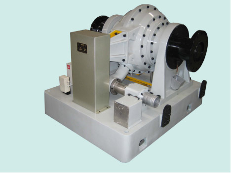
һ��Summary YP series (pressure type) hydraulic dynamometers have been widely used abroad in the 1960s and 1970s. In 1985, through license trade, China introduced the technology of Zoller Company, West Germany, to develop and produce this type of advanced dynamometer. At present, the process technology has been used in the production of a whole series of products in China. Internationally, there are Fraud in England and Cairn Company in the United States. In addition, two domestic companies have produced this series of products in small batches through imitation. Our company digests and absorbs foreign technology, carries out new optimization design and production, and can provide a full range of products.
YP series hydraulic dynamometer has 12 specifications, all of which are controlled by electric drainage butterfly valve. That is, by changing the opening of butterfly valve to change the size of absorption power. The braking power range is from 20KW to 5900KW, and the variety is complete. Domestic and foreign users choose the right type according to their engine power range.
This product is mainly used to test the effective power of various diesel engines, gasoline engines, motors and other power engines. It is an indispensable test equipment in the performance test of power engine and the efficiency test of transmission machinery.
The basic model of this product is one-way test. If users need to order with two-way test at the same time, please make a request and our company will give special customization. ����Technical specifications
1��Main features 2��Measuring performance indicators
3.Technical parameter
Table units��mm
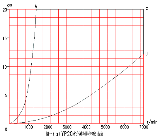
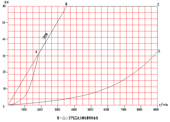
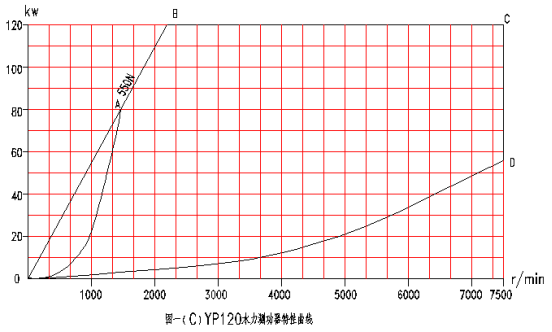
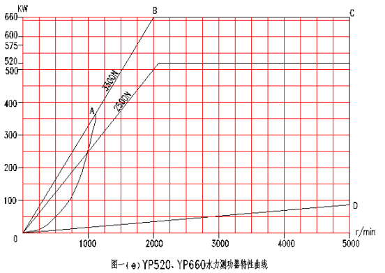
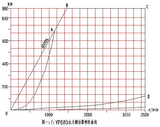
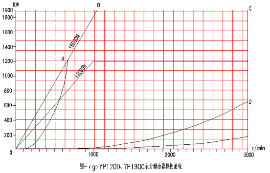
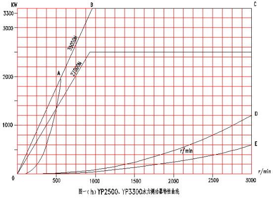
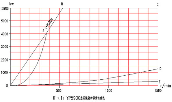
4�� characteristic curve
����Structure of dynamometer
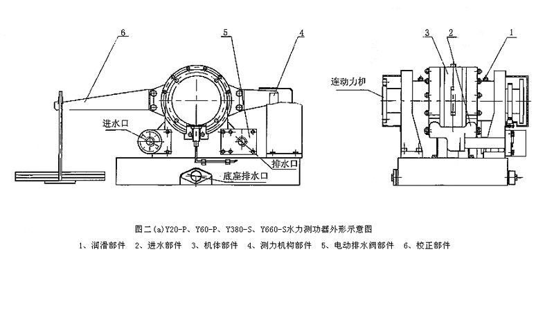
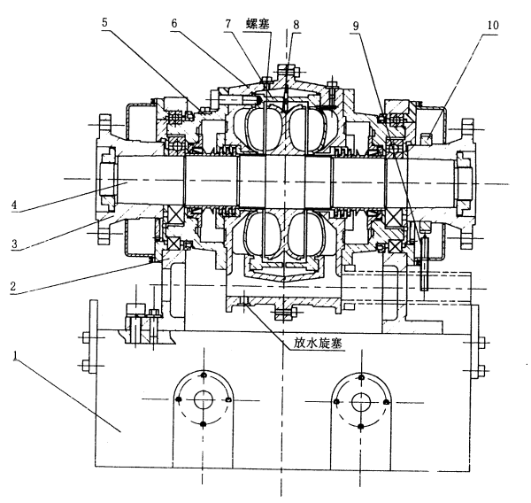
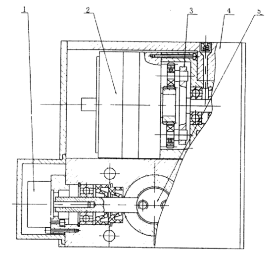
YP type hydraulic dynamometer is mainly composed of body parts, force measuring mechanism parts, intake and drainage parts, correction parts, electric drainage valve parts, automatic regulating device parts and lubricating parts. See Figures II (a), (b).
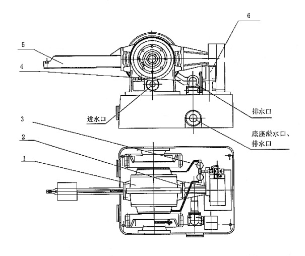
Figure two��b��Y880-S��Y1900-S��Y3300-SOutline schematic diagram of hydraulic dynamometer 1��Body parts2��Dynamometer unit 3��Lubrication parts 4��Intake and drainage components5��correcting member6��Automatic adjusting device components
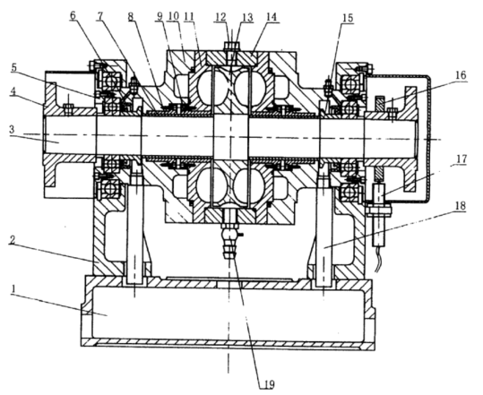
Figure three��a��YP1900Structural sketch of airframe components 1��base 2��Left and Right Bearing Seats 3��Spindle components 4��Coupling 5��Bearing plate 6. Skeleton oil seal 7, axle sleeve 8.9, bimetal axle sleeve & nbsp; 10, left and right bearing shell & nbsp; 11, left and right side shell & nbsp; 12, screw & nbsp; 13, rotor 14, shell & nbsp; 15, water seal ring & nbsp; 16, speed measuring gear & nbsp; 17, speed sensor & nbsp; 18, overflow pipe & nbsp; 19, cock
Figure three��b��YP1900Structural sketch of airframe components 1��base 2. Bearing seat 3, coupling 4, spindle component 5, bearing shell 6, shell 7, side shell 8, rotor 9, speed sensor 10, speed measuring gear
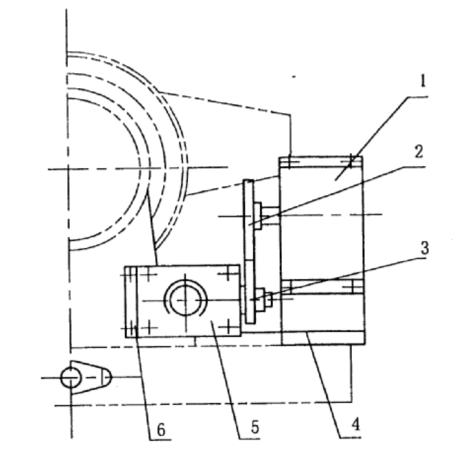
2��Force measuring mechanism components
The components of force measuring mechanism are used to measure braking force, as shown in Fig. 4 (a), (b).
It is mainly composed of brake arm, tension pressure sensor and movable bolt. The braking moment produced by the body parts is balanced with the reaction moment of the brake arm pull-up pressure sensor, and the braking force is displayed by an electronic digital display instrument. In order to protect the sensor, nylon ring or rubber ring is installed at one end of the movable plate bolt to play a buffer role. At the same time, in order to prevent the sensor from being damaged by vibration in transportation, a supporting and fixing protection device is provided. The bolt of the fixed sensor must be loosened in use, and the movable plate should be pulled to one side. If there is no movable plate, the bolt can be screwed off.
Figure four��a��YP20��YP60��YP120��YP250��YP380��YP520��YP660 Drawing of Force Measuring Mechanism Components 1. Brake arm 2, tension and pressure sensor 3, movable bolt 4, support 5, protective cover 6, movable plate 7, bolt 4 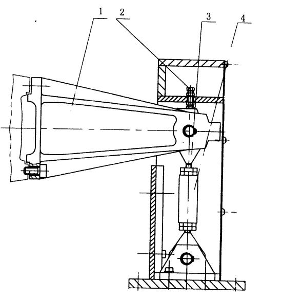
Figure four��b��YP1900Schematic diagram of dynamometer mechanism 1. Brake arm 2, fixed bolt 3, movable bolt 4, tension pressure sensor
3��Intake and drainage components
The intake and drainage components are composed of intake components and drainage components. It is mainly used for entering low temperature water and discharging high temperature water when dynamometer works. See Fig. 5 (a), (b).
YP60, YP120, YP250, YP380, YP520 and YP660 hydraulic dynamometers are composed of brackets, pipes and elbows. The elbows are connected with the left and right bearing housing of the body parts to form the intake pipeline of the dynamometer.
The drainage components are composed of brackets, pipes and elbows. The elbow is connected with the outer shell to form a drainage pipeline of dynamometer. The water thrown out by the water throwing ring in the body parts is discharged after the overflow pipe enters the base.
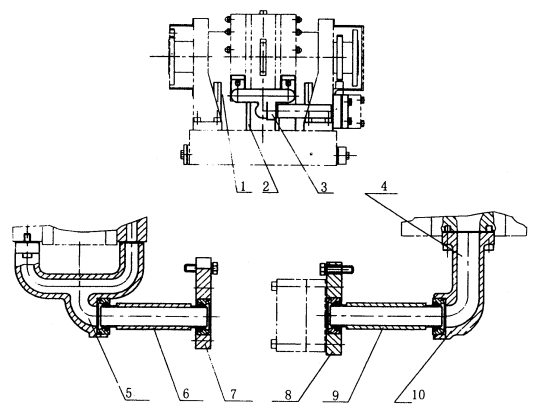
The intake parts of YP880, YP1200, YP1900, YP2500, YP3300 and YP5900 dynamometers are composed of intake valve parts and intake pipes. The drainage components are composed of a drainage butterfly valve, a drainage elbow and a drainage actuator.
Figure five��a��Drawing of Intake and Drainage Components 1. Overflow pipe 2, permeable pipe 3, intake parts (5, elbow 6, pipeline 7, bracket) 4, drainage parts (8, bracket 9, pipeline 10, elbow) 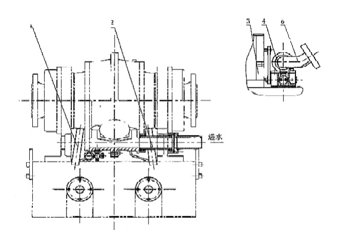
Figure five��b��Y880-S��Y1900-S��Y3300-SDrawing of Intake and Drainage Components 1. Spillway 2, Intake Component 3, Drainage Actuator 4, Drainage Butterfly Valve 5, Drainage Bend
4�� Calibration Component (Static Calibration Component)
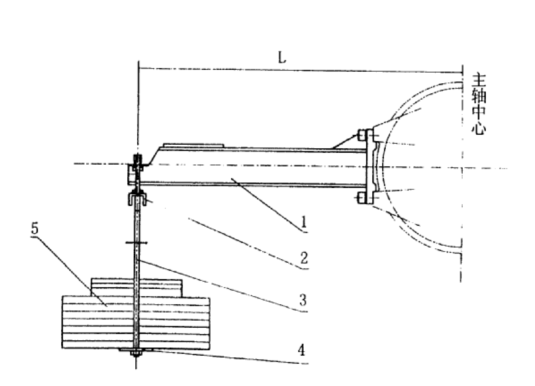
Calibration components are used for static calibration of dynamometers, as shown in Fig. 6.
It is mainly composed of calibration arm, lifting parts, suspenders, trays and weights.
The distance L from the center of dynamometer spindle to the triangular knife edge of static calibration arm and the total weight W are shown in the table below.
L and W values
Fig. 6. Schematic diagram of correction components
5. & nbsp; Electric Drainage Valve Components
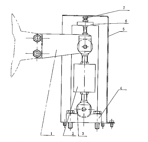
DPF electric drain valve components are used to automatically control the opening position of the drain valve, adjust the pressure of the dynamometer chamber, so that the thickness of the water ring changes with the change of working conditions, that is, to change the absorption load, as shown in figure 7.
It is mainly composed of shell, moment motor, planetary gear pair, butterfly valve, potentiometer and so on. Matching with the electronic control cabinet, the opening of the valve can be controlled by the compartment.
YP60��YP120��YP250��YP380��YP520��YP660 Hydraulic dynamometers use this form to control the drainage butterfly valve
Figure sevenDiagram of DPF Electric Drainage Valve Components 1. Potentiometer 2, Torque Motor 3, Planetary Pair 4, Shell 5, Butterfly Valve
6�� Automatic adjusting device components
The components of the automatic regulating device control the opening position of the valve slice of the drainage butterfly valve through the drainage actuator, and adjust the pressure of the inner chamber of the dynamometer to change the load, as shown in figure 8.
Fig. 8. Component sketch of automatic regulating device It is mainly composed of drainage actuator, drainage butterfly valve, supporting plate, gear pair, etc. YP880, YP1200, YP1900, YP2500, YP3300, YP5900 hydraulic dynamometers all use this form to control the drainage butterfly valve. YP880, YP1200, YP1900 dynamometers are equipped with YZ60A drainage actuator produced by our factory, YP2500, YP3300, YP5900 dynamometers are equipped with YZ20 drainage actuator.
7��Lubrication parts
Lubrication parts are mainly used for rolling bearing lubrication of dynamometer.
YP60, YP120, YP250, YP380, YP520 and YP660 hydraulic dynamometers are all lubricated with grease, and their locations are shown in Fig. 2 (a). ZL45-2 lithium-based grease can be directly injected into the pressure oiler (tanker). The specific requirements are shown in Schedule 4.
The lubrication components of YP880, YP1200, YP1900, YP2500, YP3300 and YP5900 hydraulic dynamometers are shown in Figure 2 (b). Oil mist lubrication, drip oil lubrication and pump oil lubrication can be used respectively according to user's requirements and different working conditions.
��1��Oil mist lubrication Oil mist lubrication can be used when dynamometer works at medium and high speed. Oil mist lubrication is mainly composed of gas source, pressure reducing valve, oil mist, gas pipe and so on. V-01/10 compressor can be used as gas source for a single dynamometer. Before starting the dynamometer, it is necessary to ensure the normal operation of the oil mist system. Oil mist lubrication is detailed in the instructions for the use of oil mist lubrication devices. ��2��Drip lubrication When the dynamometer works at a low speed, it can adopt drip oil lubrication instead of oil mist lubrication or pump oil lubrication. If the working speed of YP1900 hydraulic dynamometer is below 2200 r/min, and YP3300 hydraulic dynamometer is below 1800 r/min, oil drop lubrication can be used. ��3��Pump oil lubrication When the dynamometer works at a high speed, in order not to make the bearing temperature rise too high, the pump oil lubrication can be used. Pump oil lubrication is mainly composed of pumping station and inlet and outlet oil system. Pump oil lubrication must start the pump station to lubricate the bearing of dynamometer before starting the dynamometer main engine and adding water for testing. Pump oil inlet pressure can be adjusted by LI-10 throttle valve, and the pressure can be controlled in the range of 0.01-0.05 Mpa. It is suggested that as long as the working conditions are satisfied, the pressure should be as low as possible to reduce leakage.
�ġ�Working Principle and Power Calculation of Dynamometer
1�� Working principle The power machine drives the rotor components on the dynamometer spindle to rotate synchronously through the coupling, which stirs the water in the working chamber. Because of the centrifugal force produced by rotor rotation and the effect of rotor pits, water produces strong water eddy current between the side shell and the rotor pit. It gives the shell a rotating moment, so that the torque of the power machine is transmitted from the rotor to the shell. The brake arm mounted on the shell will rotate at an angle, so that the brake force is transmitted to the tension pressure sensor connected with the brake arm through the electronic digital display device. Display the braking force. The dynamometer controls the opening of butterfly valve by electric drainage valve or drainage actuator by automatic regulating device. The opening of butterfly valve is controlled by drainage actuator to change the pressure of water in the working chamber of dynamometer to change the absorption power. At the same time, the speed of dynamometer can be measured by the speed sensor and displayed on the electronic display instrument. Because it is a pressure-controlled hydraulic dynamometer and adjusts the pressure of working chamber by changing the opening of butterfly valve, the whole process must be an automatic closed-loop control system, so the pressure YP dynamometer must be equipped with an electronic control cabinet with automatic control function to operate.
2�� Calculation
��1��Power calculation
The effective power of dynamometer can be calculated by the following simple formulas when the length of statically calibrated arm is 973.8mm, guaranteed by the structure design.��
P= F n/ 10000 (Kilowatt)
Type: F--- loading (Newton)
N - Speed (Rotation/Point)
��2��Torque calculation
M=F��L (N��M)
Type��F---load��Newton��
L---Calculated arm length is 0.9549(m)
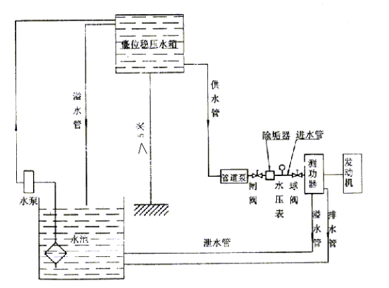
�塢Water supply system of dynamometer
The water supply of dynamometer can be used in circulating water supply system. The water supply is provided by high pressure stabilizing water tank or low pressure stabilizing water tank plus pipeline pump. Generally, the indoor water tank in the north is composed of a low-level stabilized water tank and a pipeline pump (see figure 8).
The intake pressure of dynamometer can be greater than or equal to 0.05 MPa, usually 0.05-0.15 MPa. When the dynamometer works on the full water line, it requires higher water supply pressure; when it works below the full water line, the water pressure can be lower. The water supply pressure should be kept stable, and the range of pressure fluctuation should be (+5KPa). When the dynamometer works, the water supply pressure directly affects the cavitation degree of the side shell of the dynamometer and the concave working chamber of the rotor.
In the process of dynamometer operation, water intake can not be interrupted. The water intake is about 20 liters per kilowatt hour, the drainage temperature can not exceed 70 ~C, and the general economic drainage temperature is between 55 ~60 ~C.
The circulating water supply system is mainly composed of heat sink, water pump, stabilized water tank, intake and drainage connection pipeline, water pressure meter, valve and so on. The volume of the pool should consider heat dissipation and measure the maximum power consumption, and there is a certain amount of surplus to compensate for water dissipation in the process of circulation. It is suggested that the volume of the pool should be increased as much as possible when conditions permit. The volume of water tank should be considered when the maximum water consumption is constant water supply (see the table of technical parameters for water consumption). When the water supply of the pump is larger than the maximum power consumption of the dynamometer, the volume of the stabilized tank can be recommended to be about 2-5 M3. The smaller the water consumption is, the larger the water consumption is. The volume of the tank is generally about five times that of the tank. If conditions permit, try to be as large as possible. The diameters of intake and drainage pipes should meet the requirements of the diameters of intake and drainage of dynamometers. A gate valve and a water pressure gauge shall be connected in series in the intake pipeline. The gate valve is used to regulate the intake pressure. For a fixed engine type, it usually stops moving after one adjustment. Therefore, the gate valve can be installed in any convenient position, while the ball valve on the dynamometer intake pipe is used for opening and closing water supply. Drainage pipes are generally larger than intake pipes. Drainage pipes can be circulated through clay pipes to the pool. If the user's water source is rich, it can also be discharged into the sewer. Two problems should be paid attention to in drainage pipeline: one is that the drainage can not be connected with the overflow pipe to prevent the overflow pipe from backfilling with excessive drainage pressure; the other is that if the drainage pipeline is not smooth, it will cause excessive backpressure, which will affect the normal test of dynamometer. Therefore, the pipeline arrangement should be as short as possible and with fewer elbows. The circulating water will be used as dynamometer water after descaling, which will reduce the formation of scale in dynamometer. If there is no water treatment equipment, tap water or clean river water is allowed, but no sediment and other impurities are allowed to mix in. It is not suitable to use sea water. Depending on whether the PH value of water in different areas is high or not, it is necessary to install scale remover.
Figure nine Schematic diagram of water supply system
���� Installation of dynamometers
1�� Bench Foundation
The test bench foundation is used to install dynamometers and engines. The quality of foundation design will have a great impact on the quality of test. In the design of bench foundation, the following aspects should be considered.
(1) The test-bed should be close to the side of the water source, and the distance between the foundation and the wall should be no less than 1.5 meters. Attention should be paid to the position of the calibration arm when the dynamometer is away from the wall. The whole laboratory requires good ventilation, sufficient light and lighting equipment to meet the requirements.
(2) The base of the bench should have enough mass to minimize the vibration of the bench. The foundation shall be poured with concrete of No. 90 and the proportioning shall be 1 portion of cement: 2.5 portions of yellow sand and 4 portions of stone by volume. Foundation pouring should take into account the measured object, so that the installed dynamometer can test various types of power engines. The position of foundation bolt can be constructed according to figure 10. (Fig. 10 is the foundation map of the installation of hydraulic dynamometer)
��3��Effective vibration isolation measures should be taken to reduce the transmission of vibration energy from the test bed to the outside world. The simple way is to lay a layer of yellow sand under the concrete foundation, and open a 200 mm wide and 800 mm deep anti-seismic groove around the foundation, fill it with sawdust or slag, and cover it with asphalt.
��4��Underground buried pipeline should be carried out before concrete pouring. If the exhaust pipe of power machine is installed underground, it should be more than 0.5 meters away from the pipeline.
2��Installation of dynamometer
Before tightening the anchor bolts, the dynamometer should be calibrated in two vertical directions with the installation accuracy of 1/1000 to ensure the sensitivity and correctness of dynamometer test.
3��Installation of Power Machine
Power machine should be installed according to the requirements of power machine. For some benches with changeable power model, it is better to install the power machine on the accessory bracket with three degrees of freedom (which is supplied by our factory), so as to make the installation and adjustment more convenient. When installing the throttle actuator in the engine, it is necessary to ensure that the stroke of the engine speed control handle is within the stroke of the throttle actuator.
4��Join
Universal coupling or elastic coupling should be used to connect dynamometer with power motor. When using rigid coupling, special attention should be paid to the coaxiality of two-axis installation. Generally, the coaxiality should be within 0.05 mm.
No matter which connection mode, the additional moment and axial force acting on dynamometer should be reduced as far as possible, so as not to cause fever, equipment and life accidents, so that normal testing can not be carried out. It is suggested that an auxiliary support should be installed near the end of dynamometer, which is a better method.
No matter which connection mode, the additional moment and axial force acting on dynamometer should be reduced as far as possible, so as not to cause fever, equipment and life accidents, so that normal testing can not be carried out. It is suggested that an auxiliary support should be installed near the end of dynamometer, which is a better method.
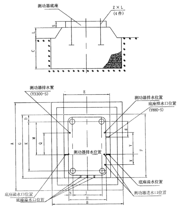
Fig. 10 Foundation Map for Installation of Hydraulic Dynamometer
The dimensions, intake and drainage diameters and locations of the installation foundation are shown in the table. List of Foundation Dimensions for Installation of YP Hydraulic Dynamometer and Location of Overflow and Drainage Port of Dynamometer Base
List of Intake and Drainage Diameters and Locations of YP Hydraulic Dynamometer
The table is not marked in millimetres.
�ߡ�Calibration of Dynamometer
Static arm is generally designed as 973.8mm. Put 1 kilogram of weights on the weighting tray and display 10 Newtons correspondingly; 2 kilograms show 20 Newtons....
For structural reasons, if the arm length is enlarged or reduced to a certain magnification, the display value should also be enlarged or reduced to the same magnification.
The specific operation is as follows:
1. Install static calibration tools: calibration arm and hanging basket;
2��For digital calibration of instrument, please read EMC900 instruction for calibration operation.
3��Remove the calibration tool at the end of calibration.
4��EMC900 controller must be restarted until the end of 100 seconds countdown.
�ˡ�Use of dynamometer
1��Before boot
��1�� Loosen the bolt of the sensor protection device to make the stator free. (2) Check the connection between coupling and spindle. (3) Check the coaxiality of the power machine and dynamometer. (4) Check the connection and circulation of the inlet and outlet pipe systems. (5) Clean the appearance, add lubricating oil to each lubrication point, and rotate the spindle to check whether the rotor and other components have collision and rotation inflexibility. (6) The calibration meets the requirements. (7) Fully open drainage butterfly valve (minimum load position). 2. Start-up test (1) Start the power machine to drive the dynamometer spindle to rotate at the same speed. After the power machine is running normally, the test can be carried out. (2) Fully open the intake valve and adjust the opening of the drainage butterfly valve until it is consistent with the working condition of the power engine. (3) Four control modes, namely, constant position, constant torque, square torque and constant speed, can be selected to control the electronic control cabinet matched with dynamometer in the test of engine external characteristics, speed regulation characteristics, load characteristics and other characteristics. (4) For some engines, sometimes the water supply pressure of a fixed dynamometer can not meet the test requirements of all working conditions, which can adjust the water supply pressure properly under different test conditions. 3. End of the experiment (1) Close the intake valve. (2) Fully open drainage valve. (3) The engine runs at low speed for several minutes and then stops. (4) Rotary sensor protection device, so that the stator is locked, the sensor is not forced. (5) Cut off the power supply connected with the electronic control cabinet. (6) Stop lubricating system oil supply. (7) If the test is not done for a long time, the bottom drain valve of dynamometer should be opened to remove the accumulated water. If conditions permit, the upper end of the shell screw (except YP1900) can be unscrewed and the accumulated water can be purged with compressed air. The position of the screw is shown in Fig. 3 (a), (b). In order to prevent bearing from entering water, please remember!!! The principle of "first start, then drain; first shut down, then shut down". To ensure that the dynamometer in the rotating state of water, but also should prevent the dynamometer in the anhydrous state of continuous operation for too long and burnt the sealing parts. (Require anhydrous working time is not more than 2 minutes.) | |||||||||||||||||||||||||||||||||||||||||||||||||||||||||||||||||||||||||||||||||||||||||||||||||||||||||||||||||||||||||||||||||||||||||||||||||||||||||||||||||||||||||||||||||||||||||||||||||||||||||||||||||||||||||||||||||||||||||||||||||||||||||||||||||||||||||||||||||||||||||||||||||||||||||||||||||||||||||||||||||||||||||||||||||||||||||||||||||||||||||||||||||||||||||||||||||||||||||||||||||||||||||||||||||||||||||||||||||||||||||||||||||||||||
| ��Refresh����Favorites����Print�� ��Close�� | |||||||||||||||||||||||||||||||||||||||||||||||||||||||||||||||||||||||||||||||||||||||||||||||||||||||||||||||||||||||||||||||||||||||||||||||||||||||||||||||||||||||||||||||||||||||||||||||||||||||||||||||||||||||||||||||||||||||||||||||||||||||||||||||||||||||||||||||||||||||||||||||||||||||||||||||||||||||||||||||||||||||||||||||||||||||||||||||||||||||||||||||||||||||||||||||||||||||||||||||||||||||||||||||||||||||||||||||||||||||||||||||||||||||
| Previous: NoNext��YPS type unidirectional hydraulic dynamometer |
- Torque speed sensor
- torque speed sensor
- Magnetic powder clutch
- Magnetic powder brake
- Tension control system
- Deviation control system
- Safety chuck
- Air shaft
- Eddy current brake
- Hysteresis brake
- Hysteresis clutch
- Hysteresis dynamometer
- Eddy current dynamometer
- Magnetic powder dynamometer
- Electric dynamometer
- Chassis dynamometer
- Hydraulic dynamometer
- Engine, axle, gearbox, PTO test bench
- Motor test bench
- Reducer test bench
- Actuator, worm gear box, test bench
- RV, Harmonic and Planetary Test Bench
- Traction machine test bench
- Drill pipe test bench
- Hydraulic wrench test bench
- Slewing bearing test bench
- Hydraulic pneumatic motor test bench
- New energy vehicle transmission test bench
- Non-standard custom test bench
- Acquisition instrument
- Testing software