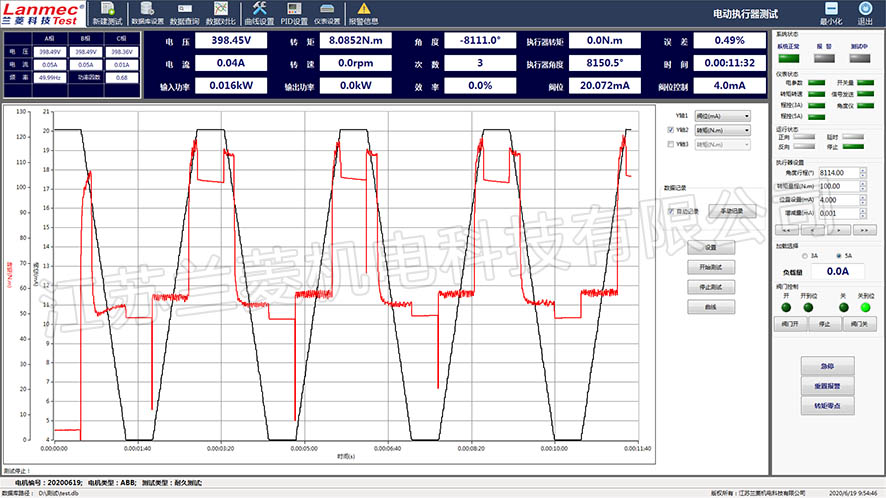
Electric actuator test interface
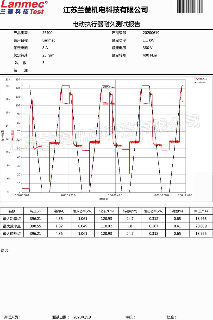
Test report of electric actuator
Actuator test bench introduction
According to the type of power source, the actuator test bench can be divided into: electric actuator test bench, pneumatic actuator test bench, hydraulic actuator test bench, shift fork pneumatic actuator test bench.
The actuator test bench can be divided into: angular travel, multi-turn, straight travel actuator test bench according to the type of motion mode.
Equipment composition
The test system consists of a loading device, a torque and speed sensor, a test bench, an actuator mounting fixture, a test cabinet, etc. It can arbitrarily change the load of the actuator under test and directly measure the output rotation of the actuator under the durable state of load Moment, speed, power, angle, pressure and other parameters.
Test parameters:
Torque: 10-100KN.m, speed≤200RPM
Test accuracy:
Electrical parameters: ±0.5% F.S (current, voltage, power factor, electrical power)
Mechanical: ±0.2% F.S (torque, speed, output power)
Efficiency: ±0.5% F.S
Angle: ±1°
Pressure: ±0.5%F.S
Software function:
The actuator test software is a data acquisition software based on PC (Windows 7 SP1) used to test the performance of the actuator. The test software can be used to manually test, automatically load, curve load, fixed-point test, endurance test and other test items of the valve under test in conjunction with electrical parameter instruments, torque and speed acquisition instruments, and program-controlled loading instruments. The data is automatically stored and the test curve is dynamically generated. Multiple curves can be selectively displayed for data comparison. The measured data are saved in a database file in the format of .db for user query. The software can export the data as PDF, Word graphic report or Excel format data file to the personal computer according to the settings.
The specific functions are as follows:
5.1 Can display, save and print:
Current, voltage, power factor, electric power input by the tested actuator
Output torque, speed, power; efficiency; rotation angle
Various parameters and the curve relationship between them, and form a report to save and print
5.2 Can display: the opening degree of the actuator, torque sensor display (2 channels 4~20mA), and calculate the dead zone of the actuator.
5.3 Can send commands to control the position of the actuator (4~20mA corresponding position);
5.4 Life test, contact output. It can send commands to command the start and stop of the cyclic action of the actuator; the panel and the host computer can switch to control the action of the actuator.
5.5 Loading method: manual, program-controlled loading
Pre-acceptance (all provided by Party B for free)
Machine acceptance
Party A provides the tested actuator, which is installed on a complete set of test benches to perform dynamic loading test, and observe whether the loading and display are normal, and whether there is abnormal vibration and noise.
Party B provides factory information:
Calibration report of torque speed sensor
Machine, instrument, software instruction manual
Software CD
Certificate of conformity, three guarantees.
Final acceptance
After the equipment has been commissioned on site by Party A, both parties will conduct final acceptance of the machine, electrical and software of the equipment. After passing the test, both parties will sign and confirm, and the unqualified items will continue to be rectified until they are qualified. (The software can be confirmed in advance during the pre-acceptance)
After-sales service
Within 12 months after the acceptance of the dynamometer (the torque and speed sensor is 24 months), if all parts and instruments fail (not caused by man-made), three guarantees will be implemented. The courier replacement that can be replaced by express delivery can be resolved by phone. The phone can't solve it. Party B needs to arrive at the site within 48 hours. For equipment failures caused by reasons other than Party B, material costs, road expenses, and labor hours will be charged at cost. After 12 months, Party B will arrive within 48 hours to use the on-site paid service.
Commissioning training
After receiving the call from Party A for debugging, Party B must arrive at the site of Party A within 48 hours, and the debugging is completed within 3 days. During this period, the operator of Party A can be trained free of charge.
|